- Shopping, made easy.
- /
- Get the app!
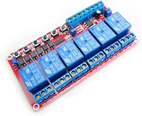
Descriptions:
Every Channel has a signal indicator can know which way switch at work
Working with self-locking / interlocking / Trigger (jog) three options.
Self-locking is to click, the relay, and then click the relay off. 6-way self-locking independent of each other, You can also add the trigger switch (CH Terminal Blocks), with high or low trigger (optional), Can simultaneously control 6 way, such as lighting control and so on.
Trigger (jog) relay when pressed, release the button to close the relay. You can also add the trigger switch (CH Terminal Blocks), with high or low trigger (optional). Applicable to such as electric doors, electric door locks, And SCM docking requires only a high or low pulse circuits circuit.
Interlock fan design is a typical application, when S1 S1 pressed the relay; When pressed S1 S2 disconnected, S2's relay. 2-way interlocking only way to turn, you can also add the trigger switch (CH Terminal Blocks), With high or low trigger (optional). Practical applications such as fans gear switch circuit.
Electrical parameters:
Trigger voltage: LOW is 0-2.5V, high defaults to 3.5-5V ( If 12V voltage trigger, you need series connection a 5.1-6.8K resistor; 24V voltage trigger, you need series connection a 15-22K resistor, otherwise it will burn the chip)
Supply voltage : 12V (DC) Maximum power consumption : 300mA
Load : 250V 10A (AC) or 30V 10A (DC)
1.DC +: Module power supply, 12V DC+
2.DC-: Module power supply , 12V DC-
3. IN1£IN6: 1-6 channel trigger relay control terminal , High or low trigger
4. TRV+: External trigger positive power supply
5. TRV-: External trigger negative power (If you want an external trigger ,please unplug the Jumpers Power RTV-and GND, TRV+ and VCC)
6. 6 micro switch: 1-6 channel relay test button, trigger effective when low
 HiLetgo 3pcs DRV8833 Dual Motor Driver Compatible with TB6612 for Arduino Microcontroller Better Than L298N
KWD 3.500
HiLetgo 3pcs DRV8833 Dual Motor Driver Compatible with TB6612 for Arduino Microcontroller Better Than L298N
KWD 3.500
 HiLetgo 5pcs L9110S DC Motor Drive Module Stepper Motor Drive Controller Board 2.5-12V H-Bridge Can Drive Dual DC Motor at The Same time or 4 Wire 2 Phase Stepper Motor
KWD 3.500
HiLetgo 5pcs L9110S DC Motor Drive Module Stepper Motor Drive Controller Board 2.5-12V H-Bridge Can Drive Dual DC Motor at The Same time or 4 Wire 2 Phase Stepper Motor
KWD 3.500
 HiLetgo MACH3 Engraving Machine CNC 5 Axis Stepper Motor Driver Interface Board With Optocoupler Isolation Blue Board + USB Cable
KWD 4
HiLetgo MACH3 Engraving Machine CNC 5 Axis Stepper Motor Driver Interface Board With Optocoupler Isolation Blue Board + USB Cable
KWD 4
 HiLetgo 2pcs DC 24V 1 Channel Relay Module with OPTO Isolation Support High or Low Level Trigger
KWD 3.500
HiLetgo 2pcs DC 24V 1 Channel Relay Module with OPTO Isolation Support High or Low Level Trigger
KWD 3.500