- Shopping, made easy.
- /
- Get the app!
"
The CRUX DKGM-16 is a premium interface for select General Motors LAN 29-Bit Vehicles. It facilitates the integration of an after-market radio to fully retain Onstar & other factory features in GM LAN 29-Bit vehicles with Bose Amplified and Non-Amplified Systems. It also includes a double-din dash kit replacement. This enhanced interface is also pre-programmed for the retention of steering wheel controls.
DIP SWITCH SETTINGS:
3.5MM SWC CABLE
Plug in the 3.5MM to 4-Pin SWC cable to the SWC module.
NOTE: Insulate the Blue/Yellow wire or 3.5mm plug if not being used.
For aftermarket radios that have wires for SWC Connections, cut off the 3.5mm plug on the CRUX SWC Cable and connect the SWC wires.
Note that there are some radios that only have SWC1 and SWC2, in this case “shield"" does not need to be connected.
SELECTING THE AUDIO SYSTEM:
If the vehicle is equipped with an amplified audio system, the DKGM-16 has a built-in audio level adaptor that outputs the proper audio level from the aftermarket radio to 8-pin connector on the DKGM-16 harness to the GRAY If the vehicle is equipped with an amplified audio system, female 8-pin connector on the DKGM-16 module.The module is also labeled “Bose” and “Non Bose” to avoid confusion. system, plug in the male 8-pin connector to the BLACK the factory amplifier female 8-pin on the DKGM-16 module
CHIME VOLUME ADJUSTMENT:
The DKGM-16 has a potentiometer to adjust the chime volume. It is set at half way by default. To adjust the volume, simply use a suitable screw driver and turn the potentiometer clockwise to increase the volume and counter-clockwise to decrease the volume.
ONSTAR VOLUME ADJUSTMENT:
To adjust the OnStar volume, turn on OnStar and adjust the volume using the Steering Wheel Control volume adjustment. Once it is set, the DKGM-16 will memorize this level.
REAR SEAT ENTERTAINMENT (RSE) (Optional Cable):
Part# CRUX2333A can be special ordered to retain the Rear Seat Entertainment (RSE).
4. Test the audio and video on the overhead screen before installing the radio back into the dashboard.
1. Connect the CRUX 2333A's 16-pin connector to the vehicle's 16-pin factory RSE connector at the radig location.
2. To view videos from the aftermarket radio on the factory overhead sereen, connect the RCAs tabeled To FACT RY OVERHEAD SCREEN to the aftermarket radio's AV output.
3. To retain the use of the factory rear panel AV input, plug the RCAs labeled AV INPUT to the aftermarket radio's AV input (optional).
BACKUP CAMERA CONNECTION:
You can retain the factory back-up camera by using the CRUX 2543 harness included in the kit.
1. Connect the 16-pin back-up camera harness to the vehicle's 16-pin factory backup camera connector.
2. Connect the Yellow video RCA to the new aftermarket radio camera input.
3. Test the video feed before installing the radio back into the dashboard.
ENABLING THE IR SYSTEM:
To retain the use of the IR headphones with the factory overhead entertainment system you will need to connect a +12 volt switched accessory power wire to the rear entertainment panel wire harness located in the rear of the center console. You will need a 1 amp fuse and a 1N4001 diode to complete the installationon. Remove the RSE control panel in the center console. Tools will be required such as a panel remover tool and/or 7mm socket. Locate the (pink) wire located in pin 14 of the (gray) connector. Connect the diode's stripe side to the pink wire. Connect the other end of the diode to one side of the 1 amp fuse. Connect the remaining side of the fuse to a +12 switched accessory wire. Refer to the wiring.
DASH KIT INSTALLATION:
A double DIN radio replacement dash kit is included in the kit to make the installation quick and easy. You have the option of installing a Double DIN or two Single DIN radios. The DKGM-16 kit includes:
INSTALLATION:
NOTE: Suzuki XL7 trim top corners of radio housing
Before installa on:
1. Locate the main trim.
2. Locate the le nd right moun ng brackets.
3. Slide the appropriate moun ng bracket into the trim ring, aligning the holes in the trim ring to the clips on the bracket.
4.For two Single DIN radio installa on, slide the stacked ISO DIN unit into the trim ring bracket assembly and secure the unit to the kit using the screws supplied with the radio
"
 Crux SWRSB-58 Radio Replacement Accessories
KWD 34
 CRUX SWRSU-38B Subaru Radio Replacement Interface
KWD 28.500
 -10%
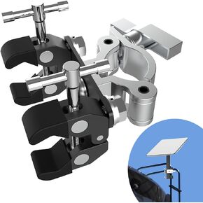
Starlink RV Ladder/Tubing Mount, Starlink Bar Mount, Starlink Pole Mount, Starlink Van Roof Rail Mount, Starlink Mounting Kit, Starlink Mount for Camper, Starlink Mounting Clamp (Not for Seaside use)
KWD 19
 Custom Install Parts Beige Radio Stereo Dash Kit w/Wire Harness+Pocket+Antenna Adapter Compatible with Chevrolet Pickup Truck 1988-1994
KWD 10.500