- Shopping, made easy.
- /
- Get the app!
Features:
1.10MHz Serial Interface
2. Individual LED Segment Control
3. Decode/No-Decode Digit Selection
4. 150µA Low-Power Shutdown (Data Retained)
5. Digital and Analog Brightness Control
6. Display Blanked on Power-Up
7. Drive Common-Cathode LED Display
8. 24-Pin DIP and SO Packages
Parameters:
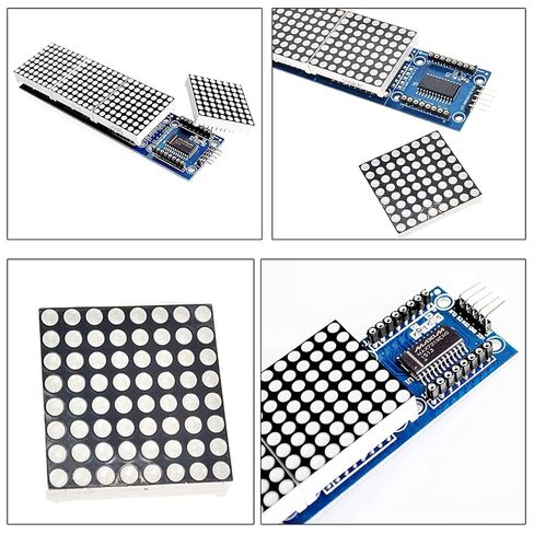
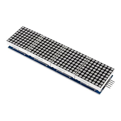
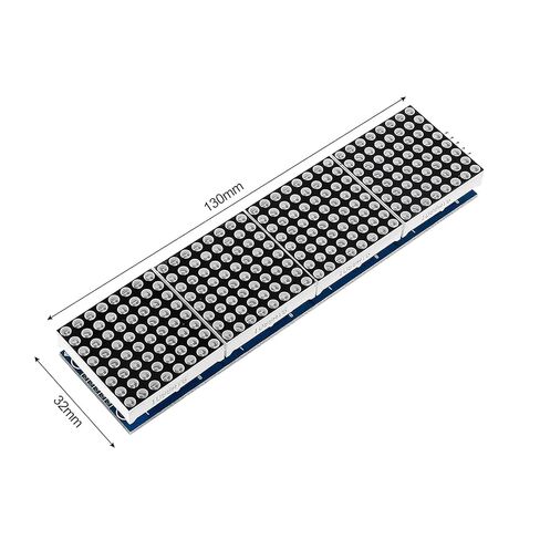
1. A single module can drive a total of 8 * 8 dot matrix overcast
2. Working voltage: 5V
3. Size: *12.8 cm*3.2 cm *1.3 cm (L*W*H)
4. With 64 fixing screw holes, diameter 3mm
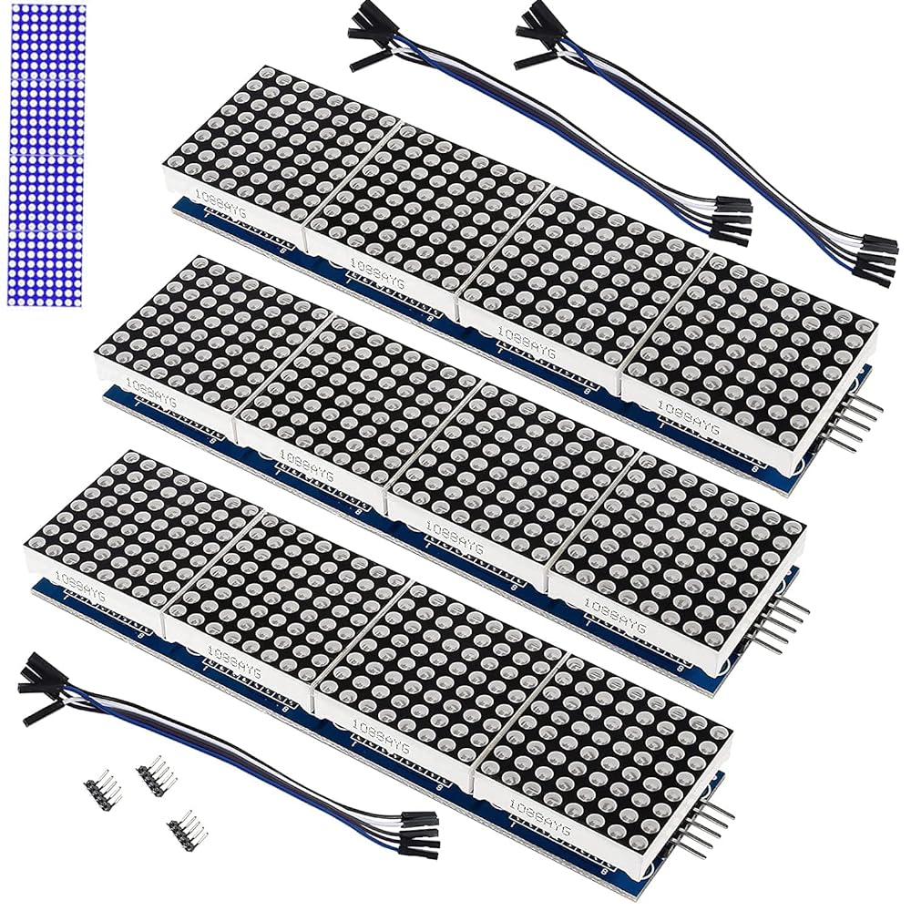
5. module with input and output interfaces, support for cascading multiple modules
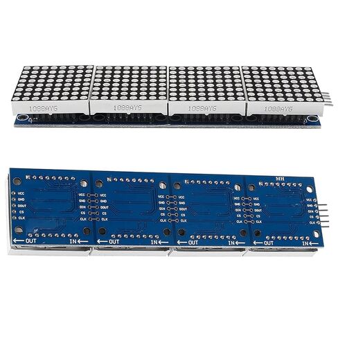
Wiring instructions:
1. The left side of the module is the input port, and the right side is the output port.
2. When controlling a single module, you only need to connect the input port to the CPU.
3. When multiple modules are cascaded, the input of the first module is connected to the CPU, the output
is connected to the input of the second module, the output of the second module is connected to the input
of the third module, and so on.
Take 51 MCU as an example:
VCC → 5V;GND → GND;DIN → P2.2;CS → P2.1;CLK → P2.0
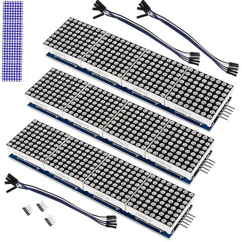
Package included:
3 x dot matrix module
3 x 5 Pin DuPont line
 ACEIRMC 6pcs INA219 I2C Bi-Directional DC Current Power Supply Sensor Breakout Module Compatible with Arduino Raspberry Pi
KWD 7
ACEIRMC 6pcs INA219 I2C Bi-Directional DC Current Power Supply Sensor Breakout Module Compatible with Arduino Raspberry Pi
KWD 7
 waveshare 2.8inch Capacitive Touch Display Compatible with Raspberry Pi 4B/3B+/3A+/CM3+/4 480×640 Resolution DSI Interface IPS Optical Bonding Screen
KWD 20.500
waveshare 2.8inch Capacitive Touch Display Compatible with Raspberry Pi 4B/3B+/3A+/CM3+/4 480×640 Resolution DSI Interface IPS Optical Bonding Screen
KWD 20.500
 ALMOCN 3 Set 3.3V 5V MB102 Breadboard Power Supply Module DC 6.5-12V USB + Male DC Power Pigtail Cable 12V 5A for Arduino Solderless Bread Board
KWD 4
ALMOCN 3 Set 3.3V 5V MB102 Breadboard Power Supply Module DC 6.5-12V USB + Male DC Power Pigtail Cable 12V 5A for Arduino Solderless Bread Board
KWD 4
 -44%
Adafruit Ultimate GPS Logger Shield - Includes GPS Module
KWD 14
-44%
Adafruit Ultimate GPS Logger Shield - Includes GPS Module
KWD 14