- Shopping, made easy.
- /
- Get the app!
Instructions for use:
Drive board connected to board:
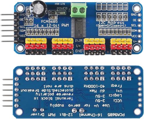
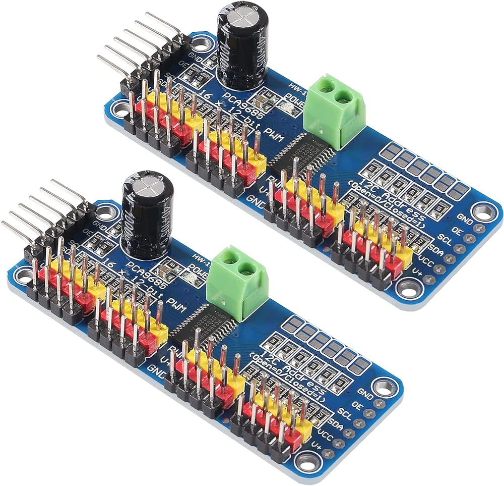
The PWM driver board uses the I2C method, so only four lines can be connected to the board: device:
"Classic" board: pin mode:
+5V -> VCC
GND -> GND
Analog 4 -> SDA
Analog 5 -> SCL
R3 and later board: pin method
(These boards have dedicated SDA and SCL pins)
+5V -> VCC
GND -> GND
SDA -> SDA
SCL -> SCL
VCC pin is only for the chip power supply, if you want to connect the servo or LED lights, use the V + pin power supply, V + pin supports 3.3 ~ 6V power supply (chip safe voltage 5V).
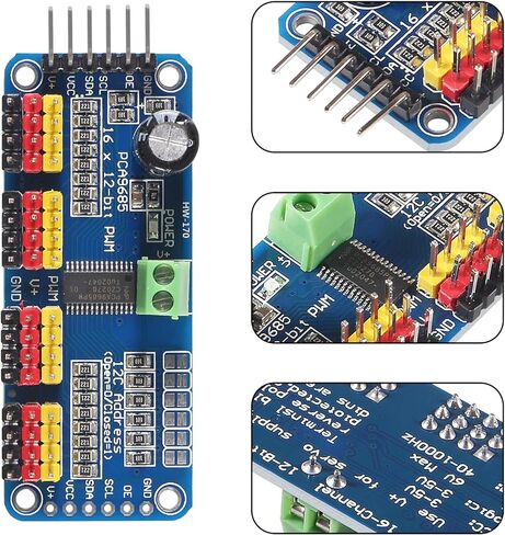
It is recommended to connect the external power supply via the power supply terminal.
power supply part:
Most of the servo design voltage is 5 ~ 6V, especially in a number of steering gear at the same time running, with the need for high-power power supply. If you are directly using the board: 5V pin to power the servo directly, there are some unpredictable problems, so we recommend that you have a suitable external power supply for the drive board.
Connect the servo:
Most servos are connected using standard 3-wire female plugs, as long as the corresponding pin into the driver board on it. (Ground wire is generally black or brown, the signal line is generally yellow or white)
for the driver board assigned address:
Each drive board of the cascade needs to have a unique access address. The initial I2C address of each driver board is 0 × 40, you can modify the upper right corner of the jumper I2C address. Connect a jumper with solder to indicate a binary number "1".
Package include:
2 x PCA9685 IIC module
 4Pcs LCD1602 Keypad Shield Module 4.5-5.5V LCD 1602 Display Expansion Shield Board Blue Backlight
KWD 5
4Pcs LCD1602 Keypad Shield Module 4.5-5.5V LCD 1602 Display Expansion Shield Board Blue Backlight
KWD 5
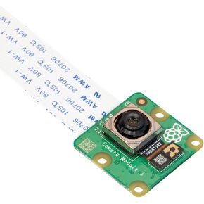 Arducam for Raspberry Pi Camera Module 3, 12MP IMX708 75°(D) Autofocus Pi Camera V3 with Acrylic Case, 15-22pin FFC Cable
KWD 19
Arducam for Raspberry Pi Camera Module 3, 12MP IMX708 75°(D) Autofocus Pi Camera V3 with Acrylic Case, 15-22pin FFC Cable
KWD 19
 5Pcs ESP32-CAM WiFi Module ESP32 Serial to WiFi ESP32 CAM Development Board 5V Bluetooth USB to Serial Port with OV2640 Camera Module
KWD 7.500
5Pcs ESP32-CAM WiFi Module ESP32 Serial to WiFi ESP32 CAM Development Board 5V Bluetooth USB to Serial Port with OV2640 Camera Module
KWD 7.500
 5PCS STM32F103C6T6 ARM STM32 Minimum System Development Learning Board Module
KWD 5.500
5PCS STM32F103C6T6 ARM STM32 Minimum System Development Learning Board Module
KWD 5.500