- Shopping, made easy.
- /
- Get the app!
Specification
Installation of the circuit
1.The components are installed from size short to high. Install size short component such as electrical resistor first and then install size high.
component. When a part of the components are installed, cut off pin of the component and then install the next part of the component.
2.There are no positive and negative poles in electrical resistor, light sensitive resistor, thermal resistor, crystal oscillator and ceramic capacitor.
3.When light sensitive resistor and thermal resistor are installed, height of 1cm should be reserved and bend it.
4.There are positive and negative poles for buzzer, the location with plus sign on the buzzer should be face with the location with plus sign on PCB.
5.After all the installation of the components are finished, and then install the integrated circuit into the tube socket, the gap location of integrated circuit and tube socket shall be aimed at PCB marked location of the gap.
6.When triode, tact switch, power socket and battery holder are installed, they should be installed correspondingly according to the shape.
After all the installation of components are finished, check again if there is any mistake in the installation, check if there are phenomena such as solder skips, cold solder joint and short circuit in the welding spot.
7.Connect pin header with numerating tube first and then weld numerating tube with PCB.
8.After making sure that there is no problem with the circuit, and then put the circuit into the shell, fix the shell with screws.
Name: Colorful Digital Clock Kit (CAI-201)
Chip: IAP15W413AS; DS1302
Material: transparent plastic
Net weight: 100g
Power supply: USB powered
Size: 140*32*40mm
Package List:
1 * Digital Talking Clock Kit
Note: (excluding CR1220 battery, 1220 battery shrapnel)

 48'' Artificial Tree Faux Ficus Tree Ficus Silk Big Plant Potted Fake House Plants Home Decor Indoor 1PC
KWD 17
48'' Artificial Tree Faux Ficus Tree Ficus Silk Big Plant Potted Fake House Plants Home Decor Indoor 1PC
KWD 17
 PH PandaHall 20 Pack Jewelry Gift Boxes, Necklace Bracelet Box Rectangle Packing Boxes with Sponge for Selling Pen Jewelry Birthday Christmas Valentines Mother Wedding Engagement 1.6x5.2x1"
KWD 8
PH PandaHall 20 Pack Jewelry Gift Boxes, Necklace Bracelet Box Rectangle Packing Boxes with Sponge for Selling Pen Jewelry Birthday Christmas Valentines Mother Wedding Engagement 1.6x5.2x1"
KWD 8
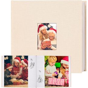 Photo Album 8x10 100 Photos with Writing Space, 8x10 Photo Album Linen Cover with Front Window, 8x10 Picture Album, 100 Photos 8x10 Photo Album Book for Wedding Kids Travel Family Baby Pictures(Black)
KWD 7.500
Photo Album 8x10 100 Photos with Writing Space, 8x10 Photo Album Linen Cover with Front Window, 8x10 Picture Album, 100 Photos 8x10 Photo Album Book for Wedding Kids Travel Family Baby Pictures(Black)
KWD 7.500
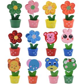 Creative Wooden Base Photo Holder - Cartoon Animal Flower Pot Table Name Number Holder Party Decoration Card Holders Picture Memo Note Photo Clip Holder (12 Pack)
KWD 5.500
Creative Wooden Base Photo Holder - Cartoon Animal Flower Pot Table Name Number Holder Party Decoration Card Holders Picture Memo Note Photo Clip Holder (12 Pack)
KWD 5.500


