- Shopping, made easy.
- /
- Get the app!
Features
1. Input voltage, output frequency signal.
2. The output signal can be fine-tuned, and the potentiometer can be adjusted to calibrate the corresponding relationship between voltage and frequency.
3. The output of this module can be supplied to the driver as a pulse signal.
When it is used with the driver, the common anode wiring is required. The relevant wiring instructions are as follows:
OC-OUT:
To connect the drive's PUL- terminal or PUL terminal 12-30V:
Connect to the PUL+ terminal of the driver or the common terminal +5V.
Technical Parameter:
Working voltage: 13.5V-30V.
Input controllable voltage range: 0-10V.
Output frequency range: 0-10KHz.
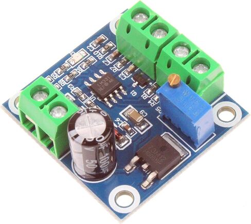
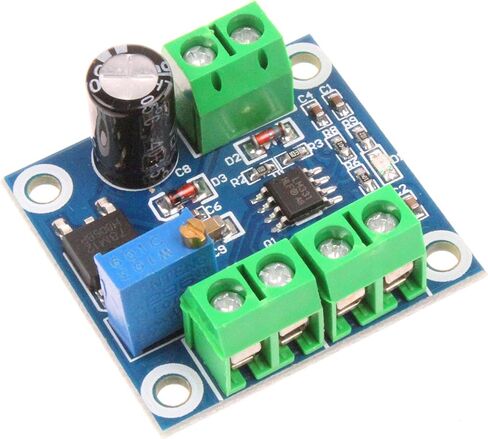
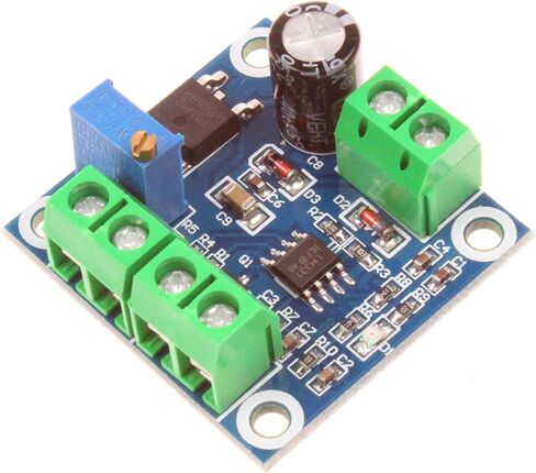
3. Hardware introduction and description
Wiring Instructions:
VCC: Power supply +.
GND: Power supply ground - .
IN+: input voltage signal +.
IN-: input voltage signal - .
OCOUT: Signal collector output port (use this output port when matching the driver). FOUT: Frequency output port (general frequency output port).
Two separate outputs, OC-OUT is NPN, FREQ-OUT is IC output.
The common cathode is used with the "-" GND of the power supply.
When the common anode is connected, it is used together with the power supply "+" VCC.
When the common anode is connected, if it is 13-24V power supply, a 2.7KR resistor should be connected in series, and if it is DC12V power supply, a 330R resistor should be connected in series.
Module Working Instructions:
Connect the positive and negative of the 0-10V voltage signal to IN+ and IN- respectively, and there is a corresponding frequency signal output between FOUT and GND.
Correspondence between input and output:
1V = 1KHz.
10V = 10KHz.
If there is a deviation in the corresponding relationship during use, you can adjust the potentiometer on the board to calibrate
Package Included:
1Pcs NOYITO Voltage to Frequency Module