- Shopping, made easy.
- /
- Get the app!
Controller Wire Color Definition:
1. Yellow, Green, Blue Single Big Head Wire: Motor Wire
2. Red-white-black-blue-green-yellow Double Row Six-wire Port: Motor Wire
3. Red and Black Single Big Head Line: Power Line
4. Red, Blue, Black, Green and Yellow Single-row Five-wire Port: Instrument Line
5. Black and Yellow Lines (two): Power off Brake Handle Line
6. Red and Black Lines: Throttle Dial Line
7. Brown-black-yellow Line: Power Sensor Line
8. Black and Red Lines (two): Headlight Lines
Meter Working Voltage: DC 24v, 36v, 48v, 60v Compatible (meter Selection Setting).
Instrument Function Description:
1. Display Function: Speed Display, Battery Indicator, Fault Indicator, Total Mileage, Single Mileage
2. Control Setting Functions: Power Switch Control, Wheel Diameter Setting, Idle Speed Automatic Sleep Time Setting, Backlight Brightness Setting, Startup Mode Setting, Drive Mode Setting, Voltage Level Setting, Controller Limit Value Setting.
3. Communication Protocol: Uart Displays All the Contents of the Screen (full Display After Power on for 1s)
3.1 Display of Battery Power and Remaining Power of Bms.
3.2 Multifunction Display Area: Total Mileage Odo, Single Mileage Trip (unit: Mile, Km), Single Boot Time Time, Battery Voltage Vol, Dst: Battery Life
3.3 Speed display Area
Avg: Average Speed, Max: Maximum Speed, Speed: Current Speed: Unit Mp/h Km/h
The Speed Signal is Taken from the Hall Signal in the Motor and Sent to the Meter by the Controller. (the Time of a Single Hall Cycle, Unit: 1ms) the Instrument Will Calculate the Real Speed According to the Wheel Diameter and Signal Data (the Number of Magnets Required by the Motor Hall)
3.4 Vehicle Power Gear Adjustment, 0-9 Digital Display and Gear Bar Display;

 uxcell DC 24V 55N 10mm Stroke Pull Push Type Open Frame Solenoid Electromagnet Linear Motion JF-1264B
KWD 10.500
uxcell DC 24V 55N 10mm Stroke Pull Push Type Open Frame Solenoid Electromagnet Linear Motion JF-1264B
KWD 10.500
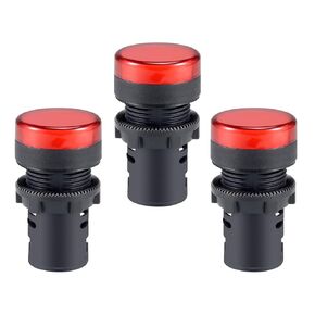 uxcell 3Pcs Red Indicator Light AC/DC 12V, 22mm Panel Mount, for Electrical Control Panel, HVAC, DIY Projects
KWD 4.500
uxcell 3Pcs Red Indicator Light AC/DC 12V, 22mm Panel Mount, for Electrical Control Panel, HVAC, DIY Projects
KWD 4.500
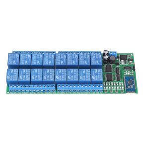 Hilitand DC 12V 16 Channel Bluetooth Relay Board Wireless Remote Control Switch for Android Phone with Bluetooth Functions
KWD 17.500
Hilitand DC 12V 16 Channel Bluetooth Relay Board Wireless Remote Control Switch for Android Phone with Bluetooth Functions
KWD 17.500
 Cutler Hammer H-1023 Overload Thermal Unit Heating Element
KWD 5
Cutler Hammer H-1023 Overload Thermal Unit Heating Element
KWD 5


