- Shopping, made easy.
- /
- Get the app!


Parameter
1.the drive terminal signal voltage:3.3-24V
2.The output voltage range:3.3-30V(output current depends on the specific situation, but the maximum is not 10MA, the total power is certain, the voltage and current are inversely proportional
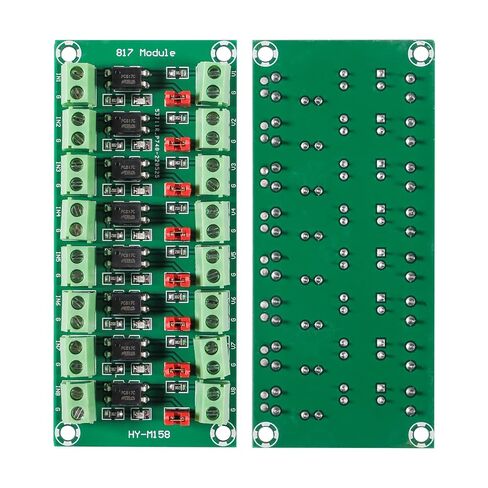
3.Through the jumper cap can achieve whether the output is high potential outputor low output.
4.The board above 2/4/8/817 are independent, can achieve simultaneous control of different voltages, etc.
1.It can realize low level driving high level and realize voltage conversion
2.Using this module, the IO voltage of the MCU can be graded to achieve isolated drive between different voltage levels
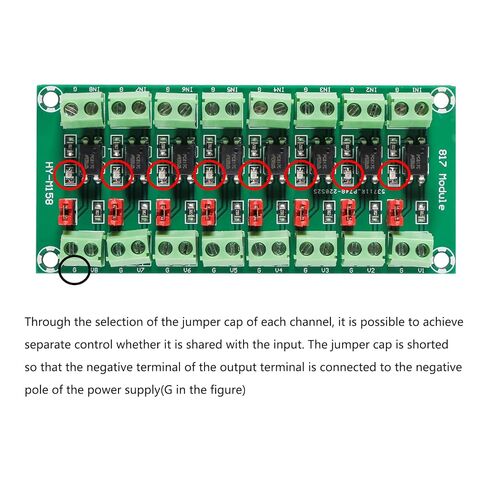
3.Through the selection of the jumper cap of each channel, it is possible to achieve separate control whether it is shared with the input. The jumper cap is shorted so that the negative terminal of the output terminal is connected to the negative pole of the power supply(G in the figure)
4.Each channel has an independent power indicator, which can be directly driven by the IO port of the MCU. The input terminal is 5V high, and the 3-5MA current can be driven.
Application:
1.MCU output level to drive the motor when the inductive device such as the motor is isolated, anti-interference protects the circuit of the MCU
2.The output level of the single-chip microcomputer is low, and the driving voltage of the driven module is high. For level matching, for example, some PLC input should have 24V voltage and can be converted by this module.
3.For the inverter, the input signal can be inverted
4.Used for high voltage detection, for example: the output signal level of a sensor is 12V.
5.The voltage of the single chip is 5V. This module can be used for isolation detection.
Package included:
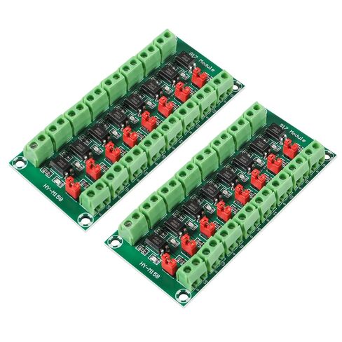
4pcs PC817 4 channel optocoupler isolation board
 6Set IR Infrared Transmitter Module Ir Digital 38khz Infrared Receiver Sensor Module for Electronic Building Block
KWD 5
6Set IR Infrared Transmitter Module Ir Digital 38khz Infrared Receiver Sensor Module for Electronic Building Block
KWD 5
 FainWan ILI9341 2.8" SPI TFT LCD Display Touch Panel 240X320 Module with PCB 5V/3.3V STM32 with Touch
KWD 9.500
FainWan ILI9341 2.8" SPI TFT LCD Display Touch Panel 240X320 Module with PCB 5V/3.3V STM32 with Touch
KWD 9.500
 Major Brands H11AA1 Optocoupler AC Input 1 Channel Transistor with Base DC Output, 6-Pin, 6.86 mm W x 5.08 mm H x 8.89 mm L, Black (Pack of 10)
KWD 6
Major Brands H11AA1 Optocoupler AC Input 1 Channel Transistor with Base DC Output, 6-Pin, 6.86 mm W x 5.08 mm H x 8.89 mm L, Black (Pack of 10)
KWD 6
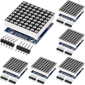 6pcs MAX7219 8x8 Dot Matrix LED Display Module 5V MCU Control MAX7219 88 LED Dot Matrix DIY Kit (6 PCS)
KWD 4.500
6pcs MAX7219 8x8 Dot Matrix LED Display Module 5V MCU Control MAX7219 88 LED Dot Matrix DIY Kit (6 PCS)
KWD 4.500