- Shopping, made easy.
- /
- Get the app!
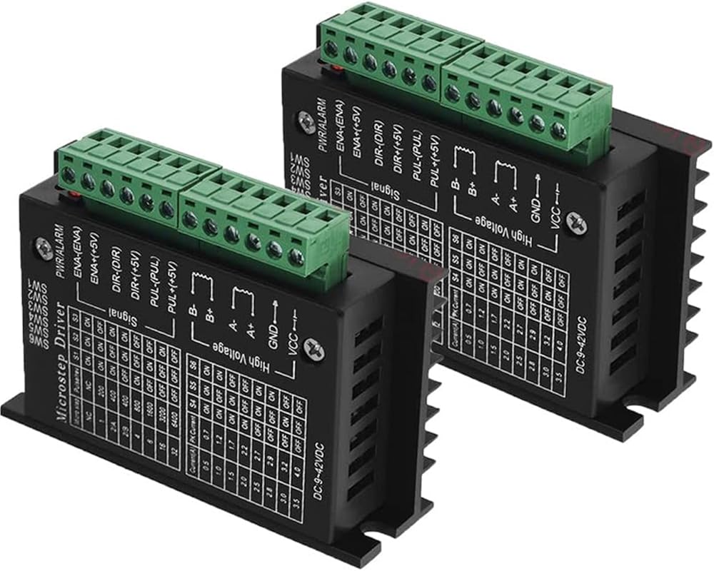
1. 9V-40V DC power supply;
2. H-bridge bipolar constant phase current drive;
3. Eight output currents up to 4.0A are available;
4. Six subdivision modes with a maximum of 32 subdivisions are optional;
5. High-speed photoelectric isolation of input signal;
6. Standard common anode single pulse interface;
7. Offline retention function;
8. The semi-enclosed casing can adapt to more harsh environments;
9. Provide energy-saving semi-automatic current locking function;
10. Built-in temperature protection and over-current protection.
11.201g
Terminal definition description
Signal input terminal
⑴CP+: Pulse signal input positive terminal.
⑵CP-: Pulse signal input negative terminal.
⑶DIR+: Positive terminal for motor forward and reverse control.
⑷DIR-: The negative terminal for controlling the positive and negative rotation of the motor.
⑸EN+: Positive end of motor offline control.
⑹EN-: Motor offline control negative terminal.
Motor winding connections:
⑴A+: Connect the A+ phase of the motor winding.
⑵A-: Connect the motor winding A-phase.
⑶B+: Connect the B+ phase of the motor winding.
⑷B-: Connect the B- phase of the motor winding.
Connection for operating voltage:
⑴VCC: DC power supply is positive (note: 10V
⑵GND: negative DC power supply.
Optocoupler isolation connection method at signal input end
The input signal interface has two connection methods: users can use common anode connection or common cathode connection according to needs.
1. Common anode connection method: Connect CP+, DIR+, and EN+ to the power supply of the control system respectively. If the power supply is +5V, it can be connected directly. If the power supply is greater than +5V, an external current-limiting resistor R must be added. , ensuring a driving current of 8-15mA for the optical coupling inside the driver. The pulse input signal is connected through CP-; at this time, DIR- and EN- are active at low level.
2. Common cathode connection method: Connect CP-, DIR-, and EN- to the ground terminal of the control system (SGND, isolated from the power ground); the +5V pulse input signal is added through CP+; at this time, DIR+, EN+ Active high level. The connection value of the current limiting resistor R is the same as the common anode connection.
Note: The EN end does not need to be connected. When EN is valid, the motor rotor is in a free state (offline state). At this time, you can manually turn the motor shaft to make adjustments that suit you. After manual adjustment is completed, set EN to the invalid state to continue automatic control.
 MECCANIXITY Synchronous Motor AC12V 0.9-1.1RPM 50-60Hz CW 4W D Shaft Electric Motor for Microwave Oven, Fan
KWD 5
MECCANIXITY Synchronous Motor AC12V 0.9-1.1RPM 50-60Hz CW 4W D Shaft Electric Motor for Microwave Oven, Fan
KWD 5
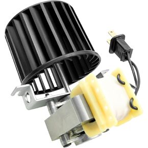 S97009796 Fan Blower Motor Assembly for Broan Bulb Heater Bathroom 162 and 164 E, G, J, K, L, M Replace 97009796 S97009796B 99080351
KWD 14
S97009796 Fan Blower Motor Assembly for Broan Bulb Heater Bathroom 162 and 164 E, G, J, K, L, M Replace 97009796 S97009796B 99080351
KWD 14
 5 HP SPL Air Compressor Motor 3450RPM Single Phase Electric Motor 56 Frame 208-230V 5/8" Shaft ODP CCW Diameter Rolled Steel Shell
KWD 87.500
5 HP SPL Air Compressor Motor 3450RPM Single Phase Electric Motor 56 Frame 208-230V 5/8" Shaft ODP CCW Diameter Rolled Steel Shell
KWD 87.500
 Packard 45117 Furnace Blower Fan Motor for Carrier HC41AE117A 1/3HP
KWD 48.500
Packard 45117 Furnace Blower Fan Motor for Carrier HC41AE117A 1/3HP
KWD 48.500