- Shopping, made easy.
- /
- Get the app!
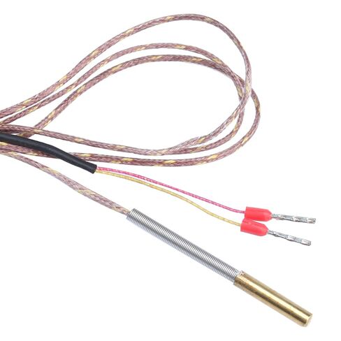
Easy to use analog output ; Temp range with 5V power: 0 to 1000℃ output (0 to 5VDC) as long as K type can handle it; Temp range with 3.3V power: 0 to 660℃ output (0 to 3.3VDC) as long as the K type can handle it ; AD8495 borad operating temp under 50°C ; Wiring: amplifier needs 0v and 5v pins to be connected to a power source, very small current requirements, so can just connect it to any 5v/3.3 and 0v pins on your controller board. This provides power to the board so it can do its amplifying. Signal output pin then needs to be connected to a spare analog input pin on your board. Look at your specific control board circuit diagram, find a pin that is currently unused that begins w/ a capital 'A'. These are usually available on expansion or auxiliary headers labelled AUX or EXP. LIKE, on a RAMPS board, you might use pin 'A3' which is located on header AUX-1. and you have to change the pin TEMP_0_PIN in your firmware. If you insist to plug the Signal output and gnd to thermistor port you have to desoldering the pullup resistor of that port. Firmware setting: ·Marlin2.0: choose “-4”in the Temperature sensors settings #define TEMP_SENSOR_0 -4 and make change in \Marlin\src\module\temperature.cpp . for mega2560 such as ramps1.4 5V 10bit ADC //#define TEMP_AD8495(RAW) ((RAW) * 6.6 * 100.0 / 1024.0 / (OVERSAMPLENR) * (TEMP_SENSOR_AD8495_GAIN) + TEMP_SENSOR_AD8495_OFFSET) #define TEMP_AD8495(RAW) ((((RAW) * 5.0 / 1024.0 / (OVERSAMPLENR)) / 0.005 / (TEMP_SENSOR_AD8495_GAIN)) + TEMP_SENSOR_AD8495_OFFSET) //for 5V 10bit ADC. For LPC1768 or otehr 32bit MCU which analog input is 3.3V 12bit ADC //#define TEMP_AD8495(RAW) ((RAW) * 6.6 * 100.0 / 1024.0 / (OVERSAMPLENR) * (TEMP_SENSOR_AD8495_GAIN) + TEMP_SENSOR_AD8495_OFFSET) #define TEMP_AD8495(RAW) ((((RAW) * 3.3 / 4096 / (OVERSAMPLENR)) / 0.005 / (TEMP_SENSOR_AD8495_GAIN)) + TEM_SENSOR_AD8495_GAIN)) + TEMP_SENSOR_AD8495_OFFSET) //for 3.3V 12bit ADC
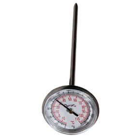 SP Bel-Art, H-B DURAC Bi-Metallic Thermometer; -10 to 110C (0 to 220F), 33mm Dial (B61310-3400)
KWD 5
SP Bel-Art, H-B DURAC Bi-Metallic Thermometer; -10 to 110C (0 to 220F), 33mm Dial (B61310-3400)
KWD 5
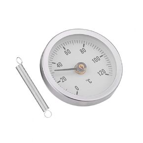 63mm Bimetal Temperature Spring Thermometer Pipe Surface IP55 Waterproof Dustproof Clip on Thermometer Pipe Temperature Gauge for Measuring Temperatures of HVAC Hot Water Pipes and Radiators
KWD 5
63mm Bimetal Temperature Spring Thermometer Pipe Surface IP55 Waterproof Dustproof Clip on Thermometer Pipe Temperature Gauge for Measuring Temperatures of HVAC Hot Water Pipes and Radiators
KWD 5
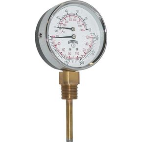 Winters TTD Series Steel Dual Scale Tridicator Thermometer with 2" Stem, 0-100psi/kpa, 3" Dial Display, ±3-2-3% Accuracy, 1/2" NPT Bottom Mount, 70-320 Deg F/C
KWD 20
Winters TTD Series Steel Dual Scale Tridicator Thermometer with 2" Stem, 0-100psi/kpa, 3" Dial Display, ±3-2-3% Accuracy, 1/2" NPT Bottom Mount, 70-320 Deg F/C
KWD 20
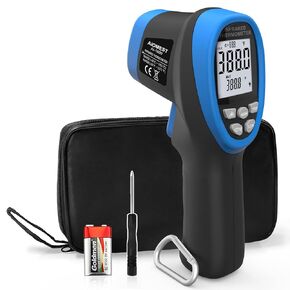 AIOMEST AI-1800 Digital Pyrometer DS 50:1, Touchless Infrared Thermometer Gun for High Temperature Non Contact Measuring -58~3,272℉,Handheld IR Laser Gauge for HVAC Kiln Cooking (NOT for Human Temp)
KWD 28.500
AIOMEST AI-1800 Digital Pyrometer DS 50:1, Touchless Infrared Thermometer Gun for High Temperature Non Contact Measuring -58~3,272℉,Handheld IR Laser Gauge for HVAC Kiln Cooking (NOT for Human Temp)
KWD 28.500