- Shopping, made easy.
- /
- Get the app!
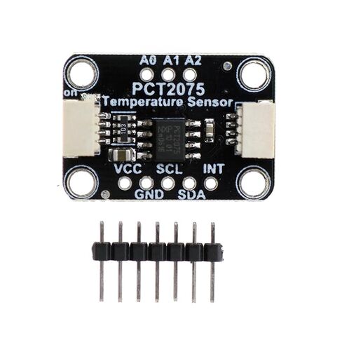
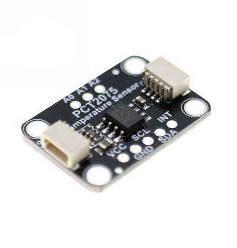
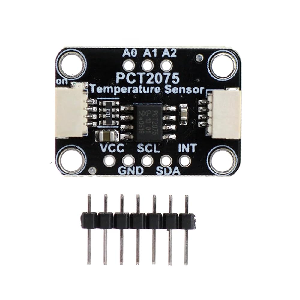
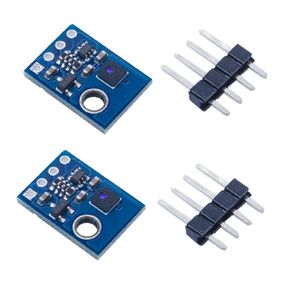
Pinout instructions:
VCC - This is the power pin. To power the circuit board, provide it with a power supply that is the same as the logic level of the microcontroller - for example, for a 5V micro like Arduino, use 5V
GND - Common ground for power and logic
I2C logic pin:
SCL - This is the I2C clock pin connected to the I2C clock line of the microcontroller.
SDA - This is the I2C data pin connected to the I2C data cable of the microcontroller
STEMA QT - These connectors allow you to connect to the development board using STEMA QT connectors or to connect to other things using various related accessories
Other pins:
INT - This is the interrupt pin. You can set PCT2075 to activate this pin when the temperature threshold is reached or exceeded.
A0, A1, A2- I2C address pins. Please refer to the "I2C Address Selection" section below.
I2C address selection:
One improvement of PCT2075 compared to its replaceable LM75 is its ability to have three times the number of I2C addresses. Interestingly, they achieve this by allowing three address pins A0, A1, and A2 to be in one of three states, low (0), high (1), or floating (F). This means there are 33 (27) possible addresses. Connect the address pin to the low level, connect the logical level of the device to the high level, or suspend the pin.
Package Included:
1 * PCT2075 Temperature Sensor Module
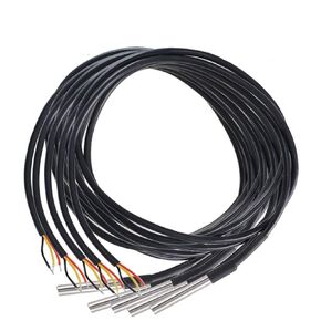 HiLetgo 5pcs DS18B20 Temperature Sensor Temperature Probe Stainless Steel Package Waterproof 1M
KWD 5
HiLetgo 5pcs DS18B20 Temperature Sensor Temperature Probe Stainless Steel Package Waterproof 1M
KWD 5
 HiLetgo DC 3-5V MAX6675 Module + K Type Thermocouple Temperature Sensor Thermocouple Sensor Set M6 Screw for Arduino
KWD 3.500
HiLetgo DC 3-5V MAX6675 Module + K Type Thermocouple Temperature Sensor Thermocouple Sensor Set M6 Screw for Arduino
KWD 3.500
 HiLetgo 2pcs AHT21 I2C IIC High Precision Digital Temperature and Humidity Sensor Module DC 2.0-5.5V DHT11 AHT10 Upgraded Version for Arduino
KWD 3
HiLetgo 2pcs AHT21 I2C IIC High Precision Digital Temperature and Humidity Sensor Module DC 2.0-5.5V DHT11 AHT10 Upgraded Version for Arduino
KWD 3
 HiLetgo 2pcs W1209 with Case 12V DC Digital Temperature Controller Board Micro Digital Thermostat -50-110°C Electronic Temperature Temp Control Module Switch with 10A One-Channel Relay and Waterproof
KWD 3.500
HiLetgo 2pcs W1209 with Case 12V DC Digital Temperature Controller Board Micro Digital Thermostat -50-110°C Electronic Temperature Temp Control Module Switch with 10A One-Channel Relay and Waterproof
KWD 3.500