- Shopping, made easy.
- /
- Get the app!
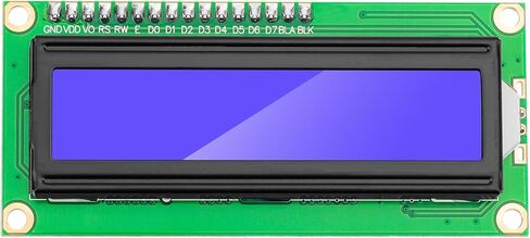
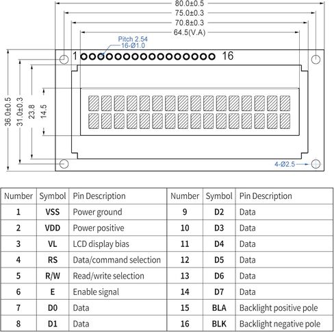
Pin Interface Description
Pin 1: VSS is the ground power supply.
Pin 2: VDD is connected to a 5V positive power supply.
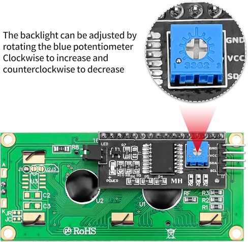
Pin 3: VL is the contrast adjustment terminal of the LCD display. The contrast is weakest when connected to a positive power supply and the highest when connected to the ground. When the contrast is too high, "ghosting" will occur. When in use, the contrast can be adjusted through a 10K potentiometer.
Pin 4: RS is the register selection. When the high level is selected, the data register is selected, and when the low level is selected, the instruction register is selected.
Pin 5: R/W is the read and write signal line. When the high level is high, the read operation is performed, and when the low level is low, the write operation is performed. When RS and R/W are both low levels, the instruction or display address can be written. When RS is low and R/W is high, the busy signal can be read. When RS is high and R/W is low, data can be written.
Pin 6: The E terminal is the enable terminal. When the E terminal jumps from high level to low level, the LCD module executes the command.
Pins 7-14: D0~D7 are 8-bit bidirectional data lines.
Pin 15: positive pole of backlight source.
Pin 16: negative pole of backlight source.
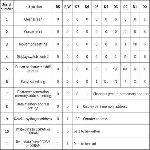
Control Instructions
1: Clear display, instruction code 01H, cursor reset to address 00H.
2: Cursor reset, cursor returns to address 00H.
3: Cursor and display mode setting I/D: cursor movement direction, high level right shift, low level left shift S: whether all text on the screen is shifted to the left or right. High level means valid, low level means invalid.
4: Display switch control. D: Control the on and off of the overall display, high level means on display, low level means off display C: Control the on and off of the cursor, high level means there is a cursor, low level means there is no cursor B: Control whether the cursor flashes, high level flashes, low level does not flash.
5: Cursor or display shift S/C: Move the displayed text when high level, move the cursor when low level.
6: Function setting command DL: 4-bit bus at high level, 8-bit bus at low level N: Single-line display at low level, double-line display at high level F: 5x7 dot matrix characters at low level, 5x10 dot matrix characters at high level.
7: Character generator RAM address setting.
8: DDRAM address setting.
9: Read busy signal and cursor address BF: Busy flag, high level means busy, the module cannot receive commands or data at this time, if it is low level, it means not busy.
10: Write data.
11: Read data.
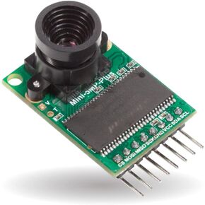 Arducam Mini Module Camera Shield 5MP Plus OV5642 Camera Module, Compatible with Arduino UNO Mega2560 Board
KWD 16.500
Arducam Mini Module Camera Shield 5MP Plus OV5642 Camera Module, Compatible with Arduino UNO Mega2560 Board
KWD 16.500
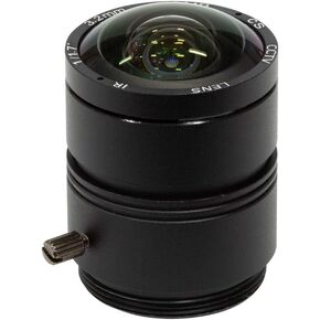 Arducam 120 Degree Ultra Wide Angle CS Lens for Raspberry Pi HQ Camera, 3.2mm Focal Length with Manual Focus
KWD 14.500
Arducam 120 Degree Ultra Wide Angle CS Lens for Raspberry Pi HQ Camera, 3.2mm Focal Length with Manual Focus
KWD 14.500
 -3%
VIGURTIME AM/FM Radio Kit | Soldering Project DIY Kit for Practicing Teaching Electronics | Stereo | Great STEM Project and Gift | Upgraded Version VT-16
KWD 14
-3%
VIGURTIME AM/FM Radio Kit | Soldering Project DIY Kit for Practicing Teaching Electronics | Stereo | Great STEM Project and Gift | Upgraded Version VT-16
KWD 14
![Adafruit MicroSD Card Breakout Board+ [ADA254]](https://cdn1.tilga.com/md/prod/3/1087/3/83148249.19506.jpg) -10%
Adafruit MicroSD Card Breakout Board+ [ADA254]
KWD 4.500
-10%
Adafruit MicroSD Card Breakout Board+ [ADA254]
KWD 4.500