- Shopping, made easy.
- /
- Get the app!
ESP32-C6-WROOM-1 is a universal module that supports 2.4 GHz Wi-Fi6, Bluetooth 5 and IEEE 802.15.4 (Zigbee 3.0 and Thread 1.3).
The module has a built-in ESP32-C6 chip.
Configure 4MB SPIflash.
ESP32-C6-WROOM-1 uses an onboard PCB antenna
Pin Header: All available GPIO pins (except the SPI bus of fash) have been led to the pin header of the development board.
5V to 3.3V LDO (5 V to 3.3V LDO): Power converter, input 5 V, output 3.3 V
3.3V Power On LED: This indicator lights up after the development board is connected to the USB power supply.
USB-to-UART Bridge: A single-chip USB-to-UART bridge that provides transmission rates up to 3Mbps.
ESP32-C6 USB Type-CPort(ESP32-C6 USB Type-C interface):
The USB Type-C interface of the ESP32-C6 chip supports USB 2.0 full-speed mode with a data transfer rate of up to 12 Mbps (note that this interface does not support the high-speed transmission mode of 480 Mbps).
This interface can be used as the power supply interface of the development board, can burn firmware to the chip, can communicate with the chip through the USB protocol, and can also be used for IT-AG debugging.
Boot Button (Boot key): Download button. Press and hold the Boot key and press the Reset key to enter the "firmware download" mode and download the firmware through the serial port.
Reset Button: Reset button.
USB Type-C to UART Port (USB Type-C to UART interface): can be used as the power supply interface of the development board, can burn firmware to the chip, and can also be used as a communication interface through the onboard USB to UART bridge and ESP32-C6 Chip communication.
RGB LED: Addressable RGB light emitting diode driven by GPI08.
ESP32-C6-DevKitC-1 powered :
1. USB Type-C to UART interface or ESP32-C6 USB Type-C interface for power supply (select one or both), default power supply method (recommended)
2.5V and GND pin header power supply
3.3V3 and GND pin header power supply
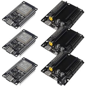
Package include:
3 x ESP32-C6-DevKitC-1 development board
Notice:
1. Please make sure to use a high-quality USB data cable. Some data cables can only be used for charging and cannot be used for data transmission and programming.
2. When using the 3V3 and GND pin headers to power the development board, you need to remove the J5 jumper and connect an ammeter in series to the external circuit to measure the module current.
 5 Set ESP32 Cam WiFi Bluetooth Development Board with OV2640 Camera Module + Micro USB to Serial Port CH340C 4.75V-5.25V Nodemcu for Raspberry Pi
KWD 10.500
5 Set ESP32 Cam WiFi Bluetooth Development Board with OV2640 Camera Module + Micro USB to Serial Port CH340C 4.75V-5.25V Nodemcu for Raspberry Pi
KWD 10.500
 -5%
3Set ESP32 ESP-32S WiFi Development Board NodeMCU-32S Microcontroller Processor Integrated with ESP32 Development Board GPIO Breakout Board 30Pin Type-C Micro USB Dual Interface ESP32 Shield 30P
KWD 9
-5%
3Set ESP32 ESP-32S WiFi Development Board NodeMCU-32S Microcontroller Processor Integrated with ESP32 Development Board GPIO Breakout Board 30Pin Type-C Micro USB Dual Interface ESP32 Shield 30P
KWD 9
 2PCS IIC I2C TWI Serial LCD 2004 20x4 Green Backlight Module with I2C Interface Adapter Compatible with Raspberry Pi R3 Mega2560
KWD 6
2PCS IIC I2C TWI Serial LCD 2004 20x4 Green Backlight Module with I2C Interface Adapter Compatible with Raspberry Pi R3 Mega2560
KWD 6
 Dorhea for Raspberry Pi 4B Case Supporting Camera Installation with Heatsinks Case Holder RPI Shell for Raspberry Pi 4B, Raspberry Pi 3 Model B+,Raspberry Pi 3 Model B, Pi 2 Model B & Pi Model B+
KWD 4.500
Dorhea for Raspberry Pi 4B Case Supporting Camera Installation with Heatsinks Case Holder RPI Shell for Raspberry Pi 4B, Raspberry Pi 3 Model B+,Raspberry Pi 3 Model B, Pi 2 Model B & Pi Model B+
KWD 4.500


