- Shopping, made easy.
- /
- Get the app!
Working Mode Introduction(P1-P7)
P0: After the signal is triggered, the relay conduction in OP time then disconnects; In the OP time, the signal is invalid.
P1: After the signal is triggered, the relay conduction in OP time then disconnects; In the OP time, the signal triggers a new timer.
P2: After the signal is triggered, the relay conduction in OP time then disconnects; In the OP time, signal trigger reset timer, relay disconnected and stop timing.
P3: After the signal is triggered, the relay disconnects the CL time, and then the relay conduction.
P4: After the signal is triggered, the relay conduction the OP time, and then the relay disconnects the CL time, and then loops the above action, gives the signal again in the loop, relays disconnect, stops the timer; and the number of cycles (LOP) can be set; End of cycle, keep relay disconnected;
P5: After the signal is triggered, the relay disconnects the CL time , and then the relay conduction the OP time, and then loops the above action, gives the signal again in the loop, relays conduction, stops the timer; and the number of cycles (LOP) can be set; End of cycle, keep relay conduction;
P6: No trigger signal after power-on, After the relay conduction OP time, the relay disconnects the CL time, and then loops the above action, signal is invalid in the loop, the number of cycles (LOP) can be set; End of cycle, keep relay disconnected;
P7: No trigger signal after power-on, After the relay disconnects the CL time, the relay conduction OP time, and then loops the above action, signal is invalid in the loop, the number of cycles (LOP) can be set; End of cycle, keep relay conduction;
(P0-P7) mode, short press the pause button, Start timing if the system is not timed ,If the system is already timed, the system pauses the timer, the relay disconnected, flashing out to indicate a reminder;
P8/P9 mode, The pause button as a trigger signal in the Run interfa
 3Pcs PCF8574 PCF8574T I2C 8 Bit IO GPIO Expander Module for Arduino & Raspberry Pi
KWD 3.500
3Pcs PCF8574 PCF8574T I2C 8 Bit IO GPIO Expander Module for Arduino & Raspberry Pi
KWD 3.500
 1Pcs SODIAL(R) 44-Pin Male IDE to SD Card Adapter
KWD 5.500
1Pcs SODIAL(R) 44-Pin Male IDE to SD Card Adapter
KWD 5.500
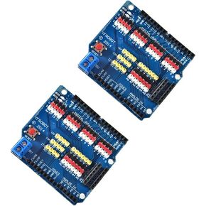 2Pcs V5 Sensor Shield Expansion Board Shield for Arduino UNO R3 V5.0 Electric Module
KWD 4.500
2Pcs V5 Sensor Shield Expansion Board Shield for Arduino UNO R3 V5.0 Electric Module
KWD 4.500
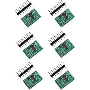 Comimark 6Pcs HX711 Weighing Sensor Dual-Channel 24 Bit Precision A/D Module Pressure Sensor
KWD 4
Comimark 6Pcs HX711 Weighing Sensor Dual-Channel 24 Bit Precision A/D Module Pressure Sensor
KWD 4


