- Shopping, made easy.
- /
- Get the app!
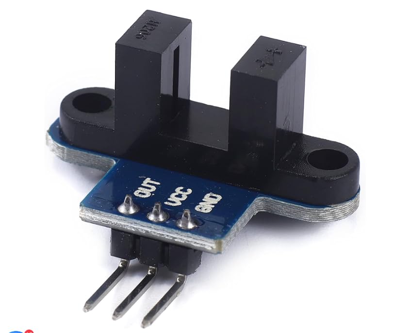
Product Usage:
✔+5 is the positive input port of the power supply, which can be connected to a voltage of 3.3V~5V.
✔GND is the negative input port of the power supply. OUT is the signal output port, which is connected to the I/O port of the microcomputer. Generally, it is connected to the external interrupt.
✔For other master boards or higher level master boards (such as Arm), if you need to set the I/O port to input/output mode, you must set it to input mode/receive mode, otherwise it can'T be used. 51 series microcontrollers can be used directly without setting input and output modes.
Product Features:
Module adopts groove to light sensor. It consists of infrared light-emitting diode and NPN photoelectric triode. The width of the groove is 5.9mm. The non-transparent object can be triggered through the slot type, the output TTL is low.
Instructions for Use:
1. After connecting the VCC and GND, the module signal indicator will be on. When there is no obstruction in the module slot, the receiving tube is turned on, and the module out outputs high level. During the cover, OUT outputs a low level and the signal indicator is destroyed.
2. Module OUT can be connected to the relay, forming functions such as limited switch, and can also be connected to the active bee lumator module to form alarm.
3. OUT output interface can be directly connected to the single -chip machine IO port. Generally, it is interrupted and detects whether the sensor is obstructed. If the motor code disk is used, the motor can detect the speed of the motor.
#Caution: Do not reverse the positive and negative terminals to avoid burning the electronic components on the board. Players should set the I/O port of MCU to input mode/receive mode, otherwise it cannot be used. For Arduino players, the I/O port of MCU must be set to input mode/receive mode, otherwise it cannot be used.
 Submersible Level Sensor, Detect Liquid Level Probe Used with Liquid Level Relay GRL8, Liquid Depth Level Meter Sensor
KWD 5.500
Submersible Level Sensor, Detect Liquid Level Probe Used with Liquid Level Relay GRL8, Liquid Depth Level Meter Sensor
KWD 5.500
 EVTSCAN Photoelectric Sensor Switch 12-24V E3HT-DS3E1 Cylindrical Diffuse Reflection
KWD 8.500
EVTSCAN Photoelectric Sensor Switch 12-24V E3HT-DS3E1 Cylindrical Diffuse Reflection
KWD 8.500
 【SINDT-485 Modbus Accelerometer】High-Accuracy 200Hz MPU6050 3-Axis Acceleration+Gyro+Quaternion+2-Axis Angle(XY 0.05° Accuracy), IP67 Waterproof Tilt Sensor for Constructions Monitoring
KWD 19.500
【SINDT-485 Modbus Accelerometer】High-Accuracy 200Hz MPU6050 3-Axis Acceleration+Gyro+Quaternion+2-Axis Angle(XY 0.05° Accuracy), IP67 Waterproof Tilt Sensor for Constructions Monitoring
KWD 19.500
 Heschen M30 Capacitive Proximity Sensor Switch, Shield Type, LJC30A3-10-Z/CY, Detection 1-10mm, 10-30VDC 200mA, PNP NO+NC, 4 Wire
KWD 5
Heschen M30 Capacitive Proximity Sensor Switch, Shield Type, LJC30A3-10-Z/CY, Detection 1-10mm, 10-30VDC 200mA, PNP NO+NC, 4 Wire
KWD 5