- Shopping, made easy.
- /
- Get the app!


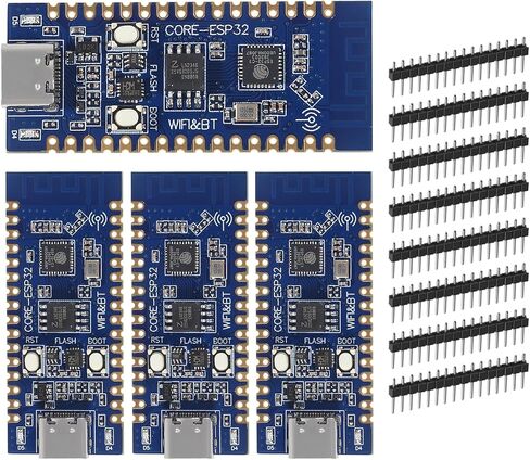
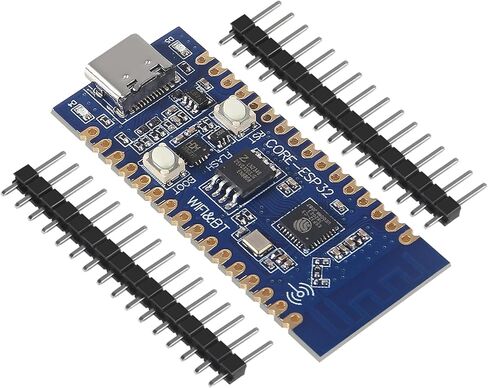
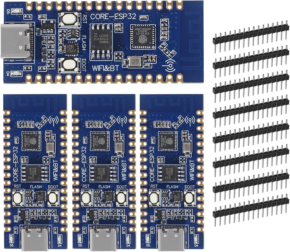
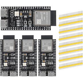
Specifications:
Size: 0.83 inches* 2.01 inches
Weight: 0.71 Oz
ROM: 384KB
FLASH: 4MB
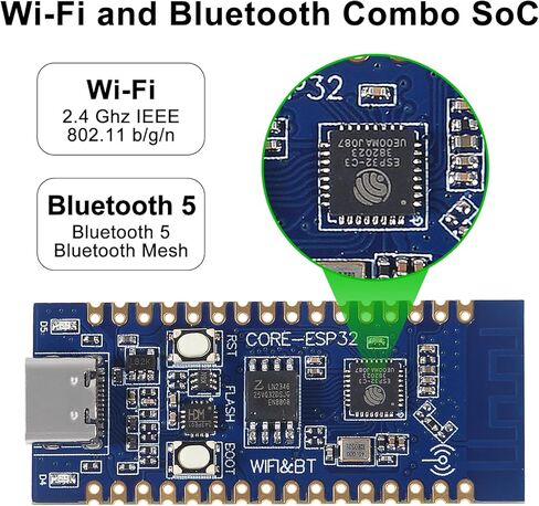
WIFI: IEE 802.11bgn
Bluetooth: BLE 5.0 & mesh
Chip: ESP32-WROOM-32
Connection: USB Type C
Antenna: PCB On-board
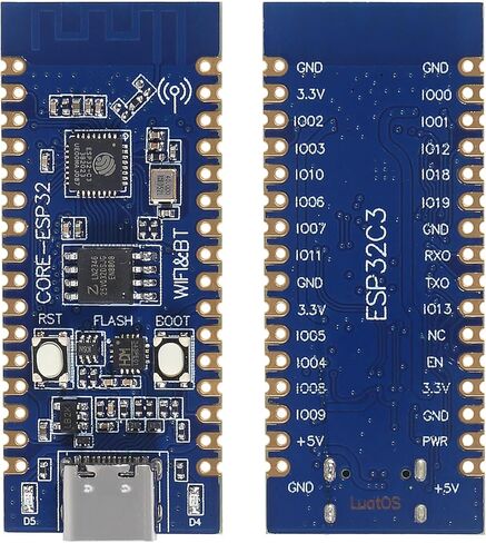
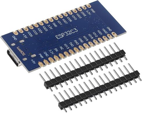
About Interface:
This development board has one SPI flash with 4MB storage capacity, which can be expanded up to 16MB.
It features 2 UART interfaces, UART0 and UART1, with UART0 serving as the download port.
There is a 5-channel 12-bit ADC on this board, with a maximum sampling rate of 100KSPS.
A low-speed SPI interface is also included in master mode.
There is an IIC controller on this board.
It has 4 PWM interfaces that can use any GPIO.
There are 15 external GPIO pins that can be multiplexed.
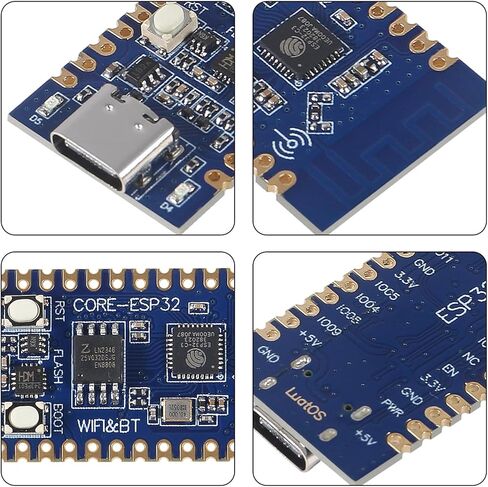
Additionally, it includes two SMD LED indicators, a reset button, a BOOT button, and a USB to TTL download debug port.
Notes:
To avoid the ESP32 from entering download mode, the BOOT (IO09) pin should not be pulled down before powering up.
It is not recommended to externally pull down the IO08 pin when designing, as this may prevent downloading via serial port when the pin is low during the download and burning process.
In QIO mode, IO12 (GPIO12) and IO13 (GPIO13) are multiplexed for SPI signals SPIHD and SPIWP, but for increased GPIO availability, the development board uses 2-wire SPI in DIO mode, and as such, IO12 and IO13 are not connected to flash. When using self-compiled software, flash must be configured to DIO mode accordingly.
Since the VDD of the external SPI flash is already connected to the 3.3V power supply system, there is no requirement for additional power supply configuration, and it can be accessed using the standard 2-wire SPI communication mode.
By default, GPIO11 serves as the VDD pin of the SPI flash, and thus requires configuration before it can be utilized as a GPIO.
 Vilros Raspberry Pi 4 2GB Basic Starter Kit with Heavy-Duty Self-Cooling Aluminum Alloy Case
KWD 39
Vilros Raspberry Pi 4 2GB Basic Starter Kit with Heavy-Duty Self-Cooling Aluminum Alloy Case
KWD 39
 XIITIA 6pcs L298N Motor Driver Controller Board Module DC Stepper Motor Dual H-Bridge for Arduino
KWD 5.500
XIITIA 6pcs L298N Motor Driver Controller Board Module DC Stepper Motor Dual H-Bridge for Arduino
KWD 5.500
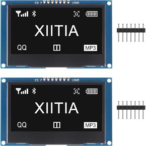 2pcs 2.42 inch 128x64 OLED LCD Display Module SSD1309 7 Pin SPI/IIC I2C Serial Interface for Arduino UNO R3 (Blue Light)
KWD 10
2pcs 2.42 inch 128x64 OLED LCD Display Module SSD1309 7 Pin SPI/IIC I2C Serial Interface for Arduino UNO R3 (Blue Light)
KWD 10
 4pcs ESP32-S3-DevKitC-1-N16R8 ESP32-S3 Development Board Wi-Fi + Bluetooth MCU Module Integrates Complete Wi-Fi and BLE Functions for Arduino
KWD 12.500
4pcs ESP32-S3-DevKitC-1-N16R8 ESP32-S3 Development Board Wi-Fi + Bluetooth MCU Module Integrates Complete Wi-Fi and BLE Functions for Arduino
KWD 12.500