- Shopping, made easy.
- /
- Get the app!

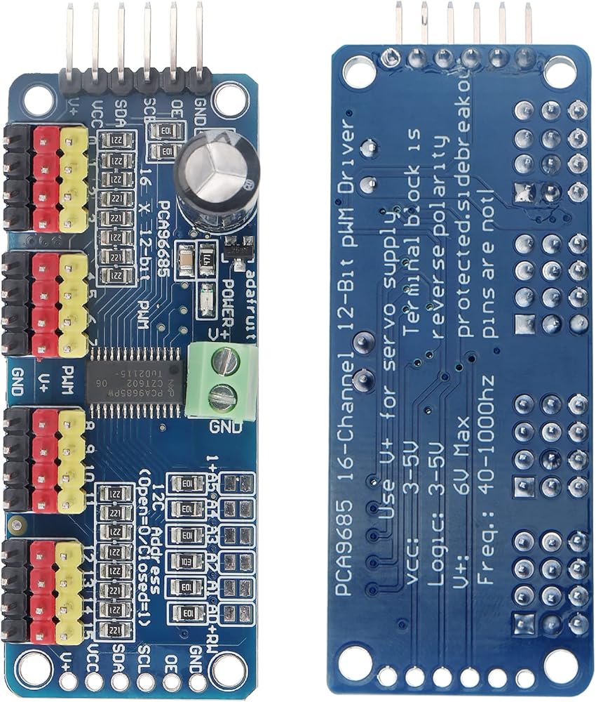
Specification:
Frequency: 40 - 1000Hz
Channel Number: 16 Channel
Resolution: 12 Bit
Voltage: DC 5 - 10V "Classic" Pin Mode Connection:
- +5V: VCC
- GND: GND
- Analog 4: SDA
- Analog 5: SCL Connection with MEGA Pins:
- +5V: VCC
- GND: GND
- Digital 20: SDA
- Digital 21: SCL Connection with Other Boards:
- +5V: VCC
- GND: GND
- SDA: SDA
- SCL: SCL
Note:
- The VCC pin only supplies power to the chip. If you want to connect a steering gear or LED lights, use the V+ pin to supply power. The V+ pin supports a power supply of 3.3 - 6V (Chip Safe Voltage: 5V). We recommend to use an external power supply through the power terminal.
Features:
- This one uses i2c communication, built-in PWM drive and a clock. This means that it will be very different from the TLC5940 series. You don't need to keep sending signals to occupy your microcontroller.
- It's 5V compatible, which means you can also control it with a 3.3V MCU and drive it safely to a 6V output (3.4+ positive voltage is fine when you want to control a white or blue indicator).
- 6 Address selection pins allow you to attach 62 driver boards to a single i2c bus for a total of 992 PWM outputs. That would be a huge resource.
- About 1.6Khz adjustable PWM output.
- For the stepper motor, the output is prepared at 12 bit resolution, which means that the update rate at 60Hz is able to achieve 4us resolution.
- Configurable push pull output or open circuit output.
- Output enable pin can quickly disable all outputs.
- Green Power indicator.
- You can insert 16 servo motors at a time in 4 sets of 3-pin connectors (servo motor plugs are slightly wider than 0.1, so you can fit 4 pairs of 0.1 connectors).
- Reverse polarity protection of input on junction board.
- A large capacitor is placed on the V+ line (which you will need in some cases). The maximum voltage of the
 MDBT50Q-512K (1pc Pak) nRF52833 Module 42 GPIO
KWD 3.500
MDBT50Q-512K (1pc Pak) nRF52833 Module 42 GPIO
KWD 3.500
 DigiYes® 10PCS MAX485 RS485 Transceiver Module TTL UART Serial to RS485 Instrument Interface Module 5V Development Accessories Board
KWD 4
DigiYes® 10PCS MAX485 RS485 Transceiver Module TTL UART Serial to RS485 Instrument Interface Module 5V Development Accessories Board
KWD 4
 DiGiYes 2 Pack L298N Motor Driver Controller Board Module Stepper Motor DC Dual H-Bridge Compatible with Smart Car Robot
KWD 3.500
DiGiYes 2 Pack L298N Motor Driver Controller Board Module Stepper Motor DC Dual H-Bridge Compatible with Smart Car Robot
KWD 3.500
 DiGiYes ESP32 S2 Mini V1.0.0 WiFi Board Based ESP32-S2FN4R2 ESP32-S2 4MB Flash Type-C Connect Fit for MicroPython
KWD 4
DiGiYes ESP32 S2 Mini V1.0.0 WiFi Board Based ESP32-S2FN4R2 ESP32-S2 4MB Flash Type-C Connect Fit for MicroPython
KWD 4