- Shopping, made easy.
- /
- Get the app!
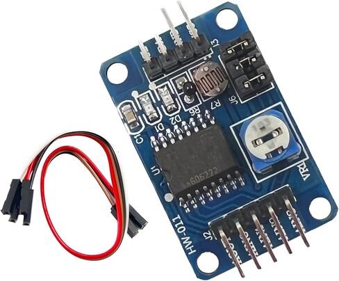
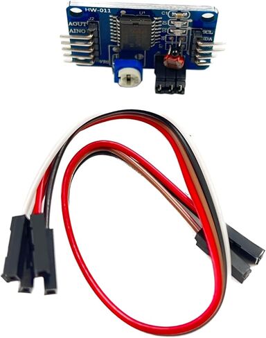
Three module interface description
The left and right side of the module, respectively, outside the expansion of 2-pin connector, respectively, as follows:
Left AOUT chip DA output interface
AINO chip analog input interface 0
AIN1 chip analog input interface 1
AIN2 chip analog input interface 2
AIN3 chip analog input interface 3
SCL IIC clock interface on the right then single-chip IO port
SDA IIC digital interface connected MCU IO port
GND module to ground
VCC power interface external 3.3v-5v
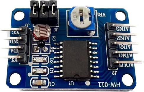
Four modules red short-circuit cap instructions
Module a total of three red short-circuit cap, respectively, as follows:
P4 connected to P4 short-circuit cap, select the thermistor access circuit
P5 connected to P5 short-circuit cap, select the photosensitive resistor access circuit
P6 connected to P6 short-circuit cap, select 0-5V adjustable voltage access circuit
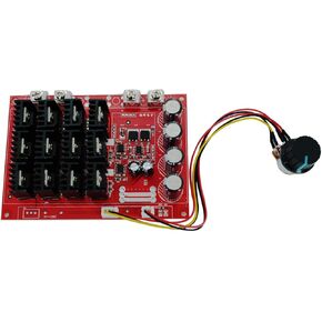 DEVMO Motor Controller,PWM DC Motor Speed Controller 10-50V 60A High Power HHO RC Driver PWM Controller Module 12V 24V 48V 3000W Extension Cord with Switch
KWD 14.500
DEVMO Motor Controller,PWM DC Motor Speed Controller 10-50V 60A High Power HHO RC Driver PWM Controller Module 12V 24V 48V 3000W Extension Cord with Switch
KWD 14.500
 DEVMO 10PCS KY-009 5050 Pwm RGB SMD LED Module 3 Color Light Compatible with Ar-duino MCU Raspberry GM
KWD 5.500
DEVMO 10PCS KY-009 5050 Pwm RGB SMD LED Module 3 Color Light Compatible with Ar-duino MCU Raspberry GM
KWD 5.500
 DEVMO BTS7960B 43A Double DC Stepper Motor Driver Module H-Bridge PWM Smart Car Compatible with Ar-duino,Raspberry Pi
KWD 6.500
DEVMO BTS7960B 43A Double DC Stepper Motor Driver Module H-Bridge PWM Smart Car Compatible with Ar-duino,Raspberry Pi
KWD 6.500
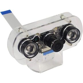 DEVMO Raspberry Pi 4B Night Vision Camera Module 5MP OV5647 Adjustable-Focus Webcam Video 1080p Compatible with Raspberry Pi 2/3 / 3 B / 3 B+ /4 /Zero&W Model B Model B+ with Case
KWD 11.500
DEVMO Raspberry Pi 4B Night Vision Camera Module 5MP OV5647 Adjustable-Focus Webcam Video 1080p Compatible with Raspberry Pi 2/3 / 3 B / 3 B+ /4 /Zero&W Model B Model B+ with Case
KWD 11.500